Ultra-Isolation Transformer
Dual electrostatic shields between primary and secondary, engineered to cut the capacitive path that common-mode noise uses to reach sensitive equipment. Specified when instruments drift, controllers reset, and nobody can find the cause.
When the problem is noise, not voltage.
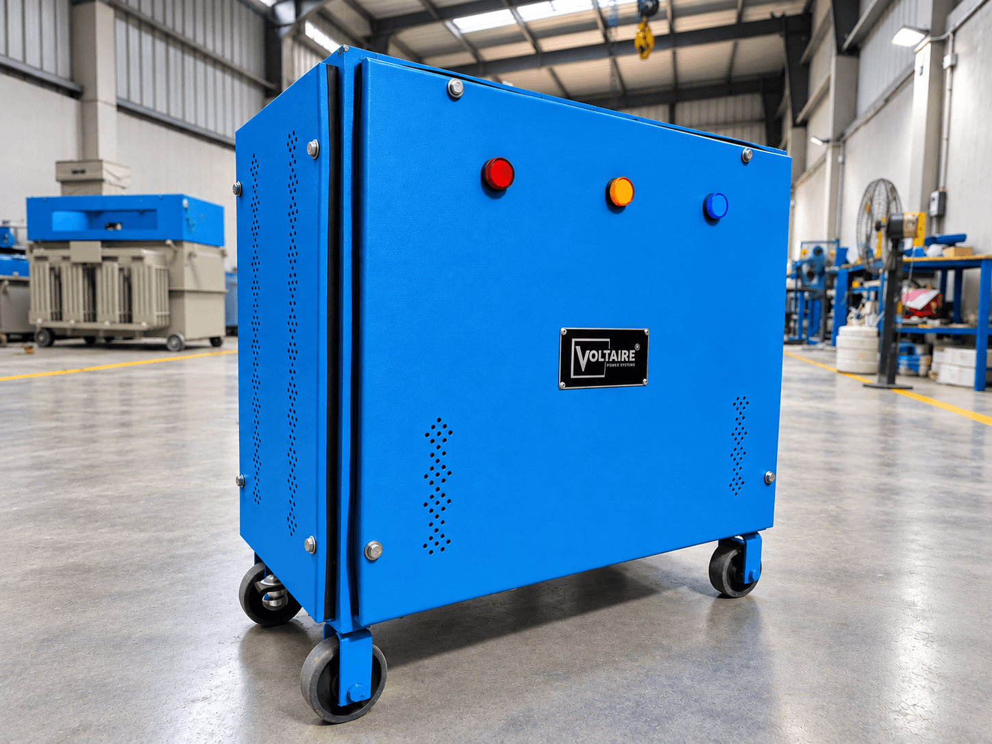
The shield, and why the earthing of it decides everything
Ultra-isolation transformers exist because standard isolation has a leak. Even with no metallic connection between primary and secondary, the two windings sit physically close to one another, and that proximity forms a capacitor. High-frequency common-mode noise — switching transients from drives and SMPS loads, transients riding in from the grid, radiated pickup — doesn't need a conductive path. It couples straight across that inter-winding capacitance and arrives on the secondary largely intact. An ultra-isolation transformer attacks this specific mechanism. Grounded electrostatic shields are placed between the windings, giving that capacitively-coupled current a deliberate low-impedance route to earth before it can reach the secondary. Where a standard unit has one shield or none, an ultra-isolation build uses dual electrostatic shields, with the winding geometry designed to minimise the residual capacitance that remains. The result is a transformer that passes power and blocks noise, rather than one that passes both.
An electrostatic shield is a conductive layer wound between primary and secondary, connected to earth. Common-mode current that would otherwise couple capacitively into the secondary instead couples into the shield, and the shield's earth connection carries it away. The transformer becomes a deliberate diversion rather than a barrier — noise is given somewhere better to go.
This makes the shield's earth connection the most important single detail of the installation, and the one most often got wrong on site. A shield bonded to a long, high-impedance, or shared earth conductor cannot dump current effectively, and the transformer under-performs its specification for reasons that have nothing to do with the transformer. A short, low-impedance, dedicated bond to a clean earth is not an installation preference here — it is the mechanism the product works by. If your ultra-isolation transformer is not performing as expected, this connection is the first thing to check.
The practical measure of all this is common-mode attenuation. We characterise every ultra-isolation build in our NABL-accredited test lab and supply the figures with the unit — treat any isolation transformer quoted without a measured attenuation figure with caution.
Ultra-isolation vs standard isolation
The decision is driven by what problem you're solving, not by budget tier. Buying ultra-isolation for a pure safety-earthing requirement is overspending; buying standard for a genuine noise problem is spending money that won't fix it.
| Ultra-Isolation | Standard Isolation | |
|---|---|---|
| Shielding | Dual electrostatic shields, earthed | Single shield or none |
| Inter-winding capacitance | Minimised by design | Higher — noise couples across |
| Common-mode noise attenuation | Measured per unit at test, figures supplied with the unit | Limited, incidental to construction |
| Best for | Instrumentation, CNC controls, lab equipment, medical, data loads, VFD-adjacent equipment | General safety isolation and earth referencing |
| Installation sensitivity | High — shield earthing quality determines performance | Lower |
| Cost | Higher | Lower |
A useful diagnostic: if the symptom is intermittent and unexplained — controllers resetting, encoder or communication errors, instrument readings drifting without a process cause, equipment that misbehaves only when a large drive nearby starts — that symptom profile points at common-mode noise, and ultra-isolation is the right specification.
What we build
We build ultra-isolation transformers as dry-type shielded units at our Hapur facility, with dual-layer electrostatic shielding as standard and winding geometry adjusted to your load and noise environment rather than a fixed catalogue build. Each unit is tested in our NABL-accredited laboratory before dispatch, and we supply the test report — including attenuation data — with every unit. That report is a purchasing-decision differentiator a trader reselling someone else's build cannot match.
- Shield configuration
- Dual-layer electrostatic shielding
- Common-mode attenuation
- Measured per unit at NABL-accredited test, reported with each unit
- Turns ratio
- 1:1 (other ratios built to order)
- Construction
- Dry type, Class F or Class H insulation
- Testing
- NABL-accredited laboratory, test certificate supplied per unit
- Compliance
- ISO 9001:2015 · CE marked
Capacity range
Our ultra-isolation range currently centres on a 50 kVA three-phase unit in regular production, built within the same 1 kVA – 500 kVA overall range we manufacture standard isolation transformers in. Sizing an ultra-isolation transformer follows the same rules as any isolation transformer, with one addition: heavily non-linear loads draw harmonic current that produces additional winding and eddy-current heating, so the unit must be derated or built to an appropriate K-factor. Send us your load schedule with the non-linear proportion identified and we'll size it correctly rather than by nameplate arithmetic.
Other isolation transformer types
Ultra-Isolation isolation transformer FAQs
That depends on the frequency content of the noise and, critically, on the quality of the shield earth bond at your site. A transformer with excellent laboratory attenuation will under-perform substantially if the shield is bonded through a long or shared earth conductor. We can advise on the earthing arrangement before installation — it costs nothing to get right at the design stage and is expensive to correct afterwards.
Ultra-Isolation — related engineering reading
Background reading on power quality, earthing and voltage stability from our engineering team, including the sizing and compliance issues that come up alongside isolation.
Why Pharmaceutical Plants Cannot Afford Voltage Fluctuation
A single voltage event in a pharmaceutical facility does not just trip a machine — it can corrupt an entire batch, trigger a regulatory audit and cost lakhs in rework. This guide explains exactly why voltage stability is non-negotiable in pharma manufacturing and what facility managers need to do about it.
Read the guideCNC Machine Tripping? Here's Why a New Drive Board Won't Fix It
You've replaced the drive board. Maybe twice. The machine ran fine for two weeks, then started tripping again. The problem was never the board — and the next replacement won't fix it either. Here is what is actually causing your CNC to trip, and what will permanently stop it.
Read the guideWhy Our Factory's Machines Kept Tripping — And What a 500 kVA Servo Stabilizer Fixed
A large manufacturing facility was experiencing machine trips across multiple production lines — every day, across both shifts. The drives were checked. The machines were serviced. The problem came back every time. The cause was the power supply. Here is the full story of what we found, what we built, and what changed after installation.
Read the guideWe size to your load — not to a catalogue rating.
Send your load schedule (and single-line diagram, if you have one) and we'll confirm capacity, configuration, and lead time — with a clear explanation of every design choice.
Speak to an engineer
+91 7060709795[email protected]Direct engineer response within 24 hours.
Submit load requirements