Standard Isolation Transformer
A 1:1 isolation transformer that breaks the direct conductive path between your incoming supply and your equipment — for earth-fault safety, a clean separately derived neutral, and general noise rejection.
Galvanic separation, done properly.
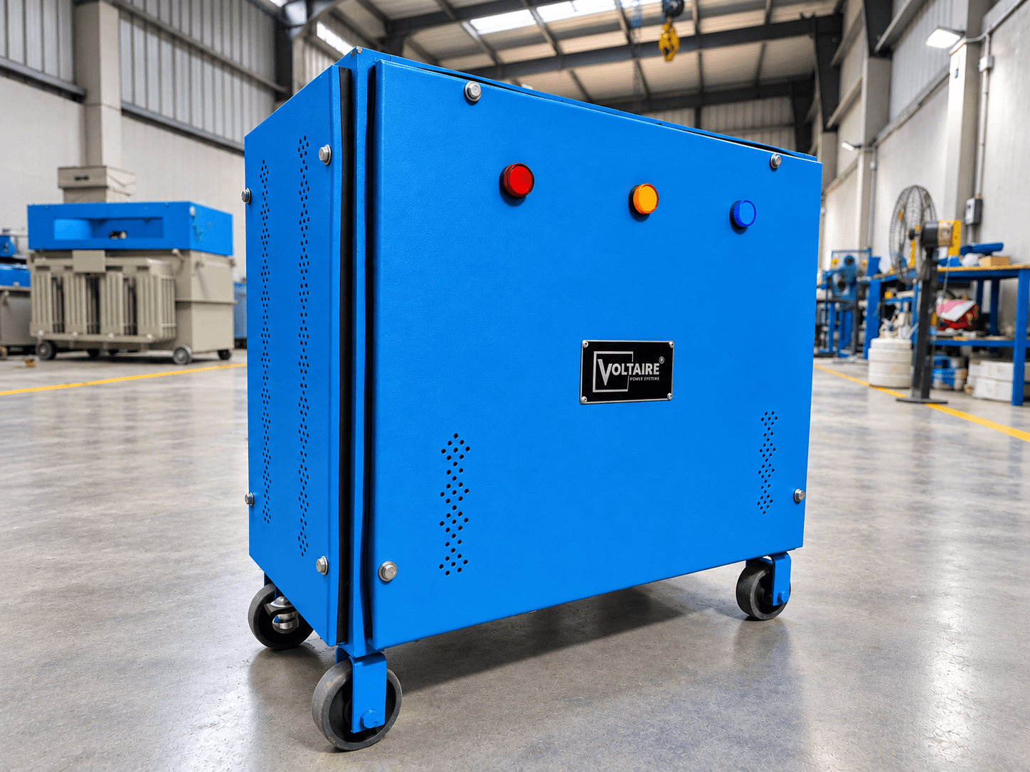
What isolation actually does to a fault
A standard isolation transformer does one fundamental thing: it transfers power between primary and secondary windings through a magnetic field alone, with no metallic connection between them. That single property — galvanic isolation — is what separates it from an autotransformer or a simple step-down unit, where primary and secondary share a winding and therefore share every fault, every earth reference, and every disturbance on the incoming line. At a 1:1 turns ratio, the voltage you put in is the voltage you get out. What changes is everything travelling alongside that voltage. Because the secondary is electrically separate from the supply, it becomes a separately derived system: you can establish a fresh neutral-to-earth bond at the transformer, giving downstream equipment a clean, local earth reference instead of inheriting whatever neutral displacement and earth-loop conditions exist across the plant. For a great deal of industrial equipment, that local earth reference is the actual reason the transformer is specified — not noise, but a defined and predictable earth.
On a conventional earthed supply, a person or a piece of equipment contacting a live conductor completes a circuit back to the supply earth, and current flows. Downstream of an isolation transformer, that return path does not exist: the secondary has no reference to the supply's earth, so a single contact with either secondary conductor does not, on its own, complete a circuit. It takes two simultaneous faults to create a hazardous path. This is why isolation transformers appear in safety codes for wet locations, test benches, and medical environments rather than purely in noise-control specifications.
The second effect is on earth loops. When two pieces of connected equipment sit on different parts of a large earthing system, small potential differences between their earth points drive circulating current through whatever signal or data cable links them. That current shows up as noise on instrumentation, as ground-loop hum on analogue signals, and as erratic communication errors on serial and control links. Isolating one of them breaks the loop.
The third is common-mode rejection. Disturbances that appear equally on line and neutral with respect to earth — switching transients, radiated pickup, drive-generated noise — pass through an unshielded transformer largely by capacitive coupling between the primary and secondary windings. A standard isolation transformer attenuates this to a degree simply by physical winding separation. Where common-mode noise is the primary problem rather than a secondary one, the shielding in an ultra-isolation transformer is the correct answer instead.
Standard vs ultra-isolation — how to tell which one you need
The two are not different quality tiers of the same product. They solve different problems, and specifying the wrong one is a common and expensive mistake.
| Standard | Ultra-Isolation | |
|---|---|---|
| Primary purpose | Safety isolation, separately derived neutral, earth-loop break | Common-mode and EMI/RFI noise suppression |
| Shielding | Single electrostatic shield or none, depending on build | Dual electrostatic shields between windings |
| Inter-winding capacitance | Higher — noise couples across more readily | Substantially lower by design |
| Typical trigger for specifying it | Earth-reference or safety requirement in the electrical design | Measured noise problem, data corruption, or sensitive instrumentation |
| Cost | Lower | Higher — more material, more build complexity |
If your requirement came from an electrical consultant's earthing design or a safety code, a standard isolation transformer is usually what was intended. If it came from a measured noise problem — instrumentation drift, communication errors, unexplained resets — specify ultra-isolation and don't expect a standard unit to fix it.
What we build
Voltaire manufactures standard isolation transformers as dry-type units at our Hapur facility — copper-wound coils on a CRGO core as standard, with aluminium winding available on request — wound, assembled, and load-tested on site. Every unit is built to the load rather than pulled from a fixed tier: we size against your actual connected load, duty cycle, and inrush characteristics before quoting. We can describe the winding because we wound it — that's the plainest difference between a factory-direct build and a trading company reselling someone else's transformer.
- Turns ratio
- 1:1 (other ratios built to order)
- Construction
- Dry type, Class F or Class H insulation
- Winding
- Copper-wound, CRGO core (aluminium available on request)
- Mounting
- Floor-mounted or panel-integrated, per project requirement
- Testing
- Load tested on site, NABL-accredited laboratory
- Compliance
- ISO 9001:2015 · CE marked
Capacity range
Voltaire builds standard isolation transformers within our overall 1 kVA – 500 kVA manufacturing range. A single-phase 10 kVA unit and a three-phase 20 kVA unit are in regular production; other ratings are built to order against your load schedule. Send us the load schedule and we'll confirm feasibility and lead time.
Other isolation transformer types
Standard isolation transformer FAQs
No. A 1:1 isolation transformer passes the input voltage through unchanged, including sags, surges, and sustained under- or over-voltage. If your supply voltage itself is unstable, you need a servo voltage stabilizer — and where both problems exist, the two are installed together, with the stabilizer correcting voltage and the isolation transformer handling isolation and noise.
Standard isolation — related engineering reading
Background reading on power quality, earthing and voltage stability from our engineering team, including the sizing and compliance issues that come up alongside isolation.
Why Pharmaceutical Plants Cannot Afford Voltage Fluctuation
A single voltage event in a pharmaceutical facility does not just trip a machine — it can corrupt an entire batch, trigger a regulatory audit and cost lakhs in rework. This guide explains exactly why voltage stability is non-negotiable in pharma manufacturing and what facility managers need to do about it.
Read the guideWhat IS 9815 Actually Means for Servo Stabilizer Buyers in India — And Why It Matters
IS 9815 is the Bureau of Indian Standards specification for automatic voltage stabilizers — and most stabilizers sold in India do not actually comply with it. Here is what the standard requires, how to verify compliance, and why it matters for your purchase decision.
Read the guideHow to Choose the Right Servo Stabilizer for Your Industry
Choosing the wrong servo stabilizer costs more than buying none at all. This practical guide walks you through every factor — KVA rating, voltage correction range, cooling type, phase selection and more — so you buy exactly what your facility needs.
Read the guideWe size to your load — not to a catalogue rating.
Send your load schedule (and single-line diagram, if you have one) and we'll confirm capacity, configuration, and lead time — with a clear explanation of every design choice.
Speak to an engineer
+91 7060709795[email protected]Direct engineer response within 24 hours.
Submit load requirements